A: The individual layers that make up optical coatings are typically a few tens of nanometers to a few hundred nanometers in thickness, while a single optical coating can be comprised of several hundred layers. Consequently, the techniques used to deposit these layers require a high degree of precision. Generally, the process begins with surface fabrication to minimize surface roughness and sub-surface damage. It continues with surface cleaning and preparation and is followed by deposition of high-performance thin film designs. The deposition technologies include thermal evaporation, electron-beam, ion-assisted deposition, and advanced plasma deposition. The most appropriate coating technology for the intended product design depends on the operating environment, spectral requirements, physical characteristics, application requirements, and economic targets. The optical coating process is completed with comprehensive performance testing using sophisticated metrology tools.
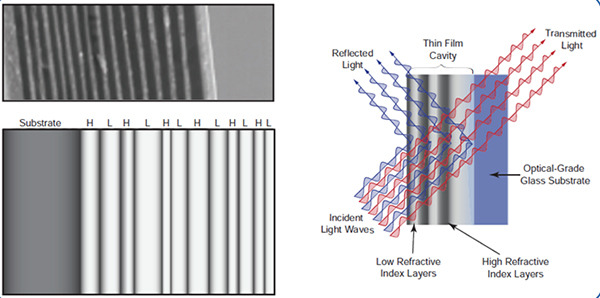
Metal coatings used on optical mirrors typically consist of a single layer approximately 100 nm thick. This ensures that the broadband high reflectivity properties of the metal due to the complex index of refraction are present. In order to provide greater tuning of the reflectivity and over specific wavelengths of interest, dielectric coatings are used . These coatings consist of alternating high refractive index (nH = 1.8 – 4.0) and low refractive index (nL = 1.3 – 1.7)
dielectric layers (see Figure 3). The thickness of each layer is chosen such that the product of the thickness and the index of refraction of the layer is λ/4.

Figure 4. Scanning electron microscope image (top) and schematic (bottom) of an optical interference coating shown on left. Reflection and transmission of light by a filter consisting of an interference coating (right).
Dielectric optical coatings are used in a myriad of ways. In addition to highly reflective dielectric mirrors (see Figure 3), these coatings are incorporated in broadband beam splitters and IR wavelength lenses. When light is incident at an angle to a surface, i.e., not normal incidence, the reflectivity becomes polarization sensitive. This allows dielectric coatings to be polarization selective and such coatings are used in polarizing beam splitters (see Section III.A.5). In addition to enhancing the reflectivity, dielectric optical coatings can also be used to reduce surface reflections in the form of broadband anti-reflection coatings. These coatings can be applied to any optical component, e.g., lens, prism, beam splitter, window, to markedly improve its transmission efficiency. The reflection from an air-glass (n2 ≈ 1.5) interface gives a reflectivity of 4%, which can be reduced considerably with a broadband anti-reflection coating (see Figure 5).

Figure 5. Typical broadband anti-reflection coating in the UV and VIS spectral regions.
These reflectivities can be reduced even more to improve transmission in laser systems with multiple optical elements, saving valuable laser energy from being lost to surface reflections. This superior performance, however, is achieved at the cost of reduced wavelength range.
Ophir® Optics Optical Coating Capabilities
*Content credit: MKS Instruments Handbook: Principals and Applications in Photonics Technologies, by the office of the CTO. 1/2019. https://www.mks.com/mks-handbook


 Ultra-High Velocity