Laser Power and Energy Measurement in High Vacuum

Efi Rotem, Ophir Laser Power Measurement

Laser power and energy measurements in high vacuum are needed in areas such as semiconductor fabrication, high energy physics, and space missions.

Designing a laser power or energy sensor for high vacuum requires knowledge and understanding of the materials and their properties in vacuum, and the necessary equipment for testing the sensor in vacuum and under laser radiation in order to evaluate the outgas rate during pump down and during laser operation.

Several challenges need to be addressed when designing laser power and energy sensors for high vacuum: outgassing, heat dissipation, signal transmission and calibration:


  • Outgassing: the sensor needs to have a low outgassing rate compatible with high vacuum systems. Furthermore, during the measurement, the outgassing rate of the sensor might increase due to heating from the absorbed laser radiation.
  • Signal transmission: the signal from the sensor needs to be connected to a meter or PC interface via a feedthrough.
  • Heat dissipation. Naturally, forced air cooling is not possible. The two practical options are conduction through the walls of the vacuum system, and closed-circuit cooling (cold finger). In any case heat management needs to be properly designed.
  • Calibration. For thermopile sensors, the main cause of difference between calibration in air and in vacuum is heat dissipation to the ambient which is present in air and not in vacuum. Photodiodes on the other hand are less sensitive to the ambient conditions.

Photodiode sensors are relatively more straight forward to work with. They have small surface area and are used for measuring low powers and thus do not heat very much during operation. Photodiodes come in TO-can or ceramic packages that normally have low outgas rate.

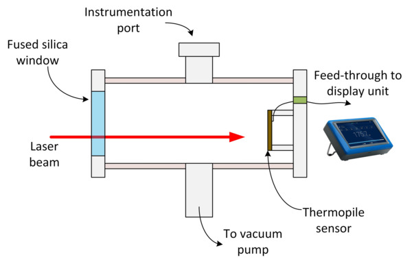
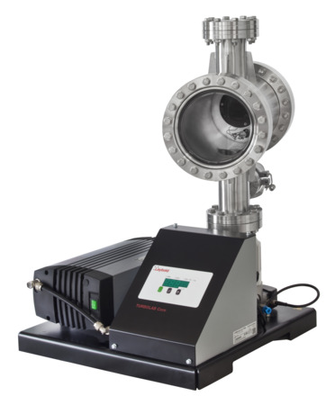
On the other hand, thermopile and pyroelectric sensors have larger surface areas and when used for measuring high power or energy may heat up. In order to qualify sensors for vacuum conditions we used a custom vacuum system shown in the following figure.

Figure 1. Vacuum system image and schematic

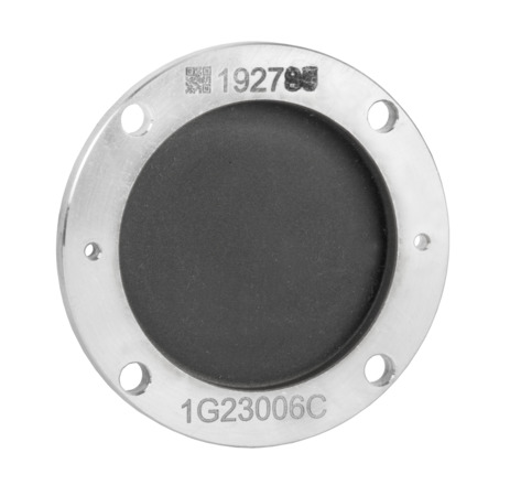
Following are two examples of tests performed with this system. The first test is a measurement of the outgassing rate of an aluminum thermopile sensor disk with a ceramic absorber coating (Ophir BB), as seen in Figure 2.

Figure 2. Thermopile absorber disk

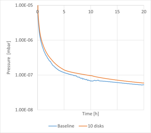
As shown in Figure 3, first, the baseline pressure is measured (in orange). Next, 10 sensor disks (in blue) were placed in the vacuum chamber. 10 disks were used in order to amplify the effect of the thermopile sensors thus making their effect more pronounced against the baseline. From this experiment we were able to extract an upper limit of 2.25*10-7 mbar/liter/s for the outgassing rate of a single thermopile sensor.

Figure 3. Thermopile sensor outgassing measurement experiment

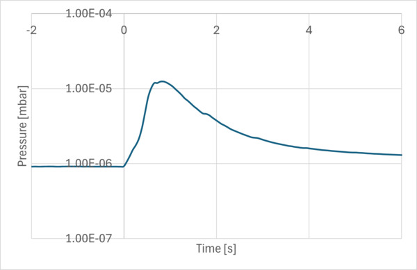
In the second experiment, we measured the effect of high energy laser pulse on the pressure inside the vacuum chamber. A copper thermopile sensor disk with a ceramic absorber coating (Ophir LP2) was mounted inside the vacuum chamber and irradiated with a 1KJ laser pulse (1KW, 1sec) at 1070nm. The sensor disk was thermally isolated on purpose in order to simulate poor heat sinking conditions. The system was pumped down to a pressure of 10-6 mbar for this experiment.

Figure 4. Pressure in the vacuum chamber

As seen in Figure 4, during the laser pulse (for 1 second), the pressure increases. This is due to a rise in the outgassing rate caused by heating of the absorber surface. The rapid pressure drop after the pulse indicates that outgassing rate has dropped and that the released gas was not absorbed by the chamber walls and was quickly removed by the vacuum pump. Proper selection of the absorber coating and heat sinking can help reduce the outgassing even further.

In conclusion, we have demonstrated a few key aspects and challenges of laser power and energy sensor design for high vacuum operation.