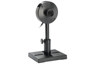
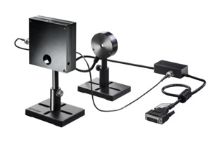
The RM9-Pyro radiometer is a sensor for measuring the power of very low level CW or quasi CW lasers and light sources. The RM9 uses a pyroelectric sensor and lock-in amplifier with an 18 Hz chopper (not included, use RMC1 or other chopper) to measure a wide range of radiation, from <100 nW to 100 mW. It has an 8mm aperture and covers the spectral range from 0.15 to 12 µm.
Pyroelectric sensor with 0.15-12 µm spectral range
100 nW to 100 mW power measurement range
Use RMC1 or other chopper and lock in amplifier for lowest noise and drift
Additional CAD file downloads are not available for this product.
rm9-pyro-radiometer - Drawings
Additional drawings are not available for this product.
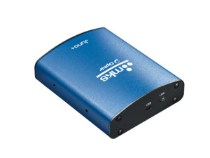
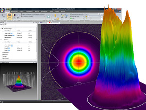
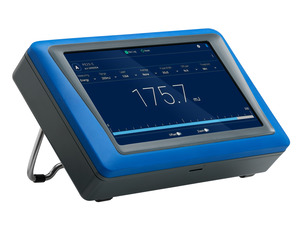
Full support available for the RM9 sensor with the Centauri, Vega, Nova II, Juno, Juno+, Juno-RS, EA-1, StarLite and StarBright and with the StarLab application.
There is limited support for the RM9 sensor with the older LaserStar, Pulsar, Quasar and Nova.
To upgrade the meters below to the version that fully supports RM9:
StarBright meters (rev 1.18 and higher) press here
Nova II / Vega meters (rev 2.44 and higher) press here
StarLite meter (rev 1.26 and higher) press here
Juno interface (rev 1.31 and higher) press here
Juno+ press here
Juno-RS press here
EA-1 press here
Centauri press here
Specifications
Product Name
RM9-Pyro
Aperture Size
Ø8 mm
Absorber Type
Pyroelectric
Spectral Range
0.15-12 µm
Minimum Power
100 nW
Maximum Average Power
100 mW
Maximum Average Power Density
5 W/cm²
Response Time
3.5 s
Dimensions
Ø62 x 21 mm
Includes Chopper
No
Cooling
Convection
CE Compliance
Yes
UKCA Compliance
Yes
China RoHS Compliance
Yes
Features
Measuring Laser Power Below the Noise Floor with a Lock-In Amplifier
Measuring optical signals in the femtowatt (10-15) to nanowatt (10-9) range can be very challenging. This video explains how Lock-In Amplifiers can help make these measurements possible.
Measure Very Low powers Over a Very Broad Spectrum with the RM9 Radiometer
The RM9 system measures powers down to 100 nW over a very broad spectral range, from UV to far IR. This video introduces you to the RM9, and shows you how to use it.
First, clean the absorber surface with a tissue, using Umicore #2 Substrate Cleaner, acetone or methanol. Then dry the surface with another tissue. Please note that a few absorbers (Pyro-BB, 10K-W, 15K-W, 16K-W and 30K-W) cannot be cleaned with this method. Instead, simply blow off the dust with clean air or nitrogen. Don't touch these absorbers. Also, HE sensors (such as the 30(150)A-HE-17) should not be cleaned with acetone.
Note: These suggestions are made without guarantee. The cleaning process may result in scratching or staining of the surface in some cases and may also change the calibration.
The various RM9 radiometer models are fully compatible with these meters/interfaces:
Vega / Nova II (firmware version 2.44 or higher)
Juno (1.31 or higher)
StarLite (1.26 or higher)
StarBright (1.18 or higher)
They are partially compatible with Ophir’s other meters (Nova, LaserStar, USBI, Pulsar, and Quasar). They will function properly with these devices, except with a narrower power range and with reduced accuracy. See specs for more details.
Yes, but keep in mind that the RM9 will measure average power, not energy. Also, pulse rates below ~50 Hz may generate additional noise. Pulse rates close to 18 Hz may cause beat frequency issues.
Yes, but it must be set to a chopping frequency of 18 Hz. If your chopper has high emissivity (black) surfaces, it should be located as far from the sensor as possible, at least 200 to 300 mm. If your chopper has low emissivity (bare metal) surfaces, care should be taken to ensure that when it blocks the laser beam it does not generate stray reflections that can reach the sensor
If your source happens to be pulsed at 18 Hz, you cannot use the chopper, since this will generate very low frequency beat signals. However, it might be possible to use the RM9 directly with your laser source, as long as you can connect a BNC sync to the RM9 sensor. Contact us about your particular application to be sure this is the right solution for you.
In theory, if a beam is completely parallel and fits within the aperture of a sensor, then it should make no difference at all what the distance is. It will be the same number of photons (ignoring absorption by the air, which is negligible except in the UV below 250nm). If, nevertheless, you do see such a distance dependence, there could be one of the following effects happening:
If you are using a thermal type power sensor, you might actually be measuring heat from the laser itself. When very close to the laser, the thermal sensor might be “feeling” the laser’s own heat. That would not, however, continue to have an effect at more than a few cm distance unless the light source is weak and the heat source is strong.
Beam geometry – The beam may not be parallel and may be diverging. Often, the lower intensity wings of the beam have greater divergence rate than the main portion of the beam. These may be missing the sensor's aperture as the distance increases. To check that you'd need to use a profiler, or perhaps a BeamTrack PPS (Power/Position/Size) sensor.
If you are measuring pulse energies with a diffuser-based pyroelectric sensor: Some users find that when they start with the sensor right up close to the laser and move it away, the readings drop sharply (typically by some 6%) over the first few cm. This is likely caused by multiple reflections between the diffuser and the laser device, which at the closest distance might be causing an incorrectly high reading. You should back off from the source by at least some 5cm, more if the beam is not too divergent.
Needless to say, it’s also important to be sure to have a steady setup. A sensor held by hand could easily be moved around involuntarily, which could cause partial or complete missing of the sensor’s aperture at increasing distance, particularly for an invisible beam.
Typical choppers have the same type of surface on both faces: either metallic, low emissivity or black, high emissivity. When blocking the laser beam, metallic surfaces will reflect or scatter a significant portion of the laser power which may result in stray reflections reaching the sensor. Black surfaces solve this issue, but if the chopper is positioned close to the RM9 or RM9-THz sensor, they will pick up a thermal signal from the chopper blades. Stray reflections and thermal signal from the blades can impair measurement accuracy. Our chopper enjoys the best of both worlds. It has a black surface that should face the laser beam and a low emissivity surface that should face the sensor.
The RM9 is only sensitive to signals chopped at 18 Hz, so placing the chopper as close to the laser source as possible will minimize stray light entering the chopper and being read as part of the signal.
The noise specification is based on a 10 second moving average. Set the power meter to average the measurements for optimal performance.
It is also recommended to zero the sensor before use. This is done by disconnecting the BNC cable between the RM9 sensor and the chopper or turning off the chopper. Then follow the regular instructions for zeroing that can found in your power meter or PC interface manual.
Accessories
Damage Threshold Test Plates (Metallic)
Test plates with same absorber coating as the sensor. For testing that laser beam is not above damage threshold (1 such plate is included with sensor package).
5m molded cable to connect PPS / Quad electronic box to power meter or interface. Order along with sensor to receive this instead of 0.5m cable from electronic box.
Compare
Description
Compatibility
Drawings, CAD & Specs
Avail.
Price
7E01176BBeamTrack Sensor Cable, 5 m Length, Connect PPS / Quad to Power Meter
UNIVERSAL
In Stock
$79
Showing 1 to 1 of 1 entries
Extended Warranty for Sensor
Customers that purchase the above items also consider the following items. Ophir-Spiricon meters and sensors include a standard manufacturers warranty for one year. Add a one year Extended Warranty to your meter or sensor, which includes one recalibration.
In order to provide better service and products, please provide the following brief information. Any future resource requests will be automatically available.
Password Reset
Enter your email address below to reset your account password.
Password Reset
Email Verification Required
Cart Items Updated
Remove Product
Remove this product from your comparison list?
Check Order Status
Provide an order number and postal code to check the status of an order or download an invoice for an order that has shipped. Login to view your complete order history.
Sign In Required
To access this and other valuable technical resources, please sign in or register for a new online account.