Measuring Non-Laser Light Sources with Commercial Laser Beam Profiling Systems

Commercially available laser beam profiling products are used throughout the world to research, develop, manufacture, and test the quality of lasers and systems that use lasers. These measurement systems are also commonly employed to test and evaluate the spatial intensity distribution of other light sources.

Author:

Kevin Kirkham, Senior Manager, Product Development, Ophir-Spiricon, LLC

Laser beam profiling products are typically composed of a 2-dimensional sensor array, optical imaging and attenuation optics, and software that displays, analyzes, and records the visual representations of the distribution of light for measurement, archival, and retrieval. The heart of a laser beam profiling system is a scientific grade CCD or CMOS camera. The camera is selected and tested for linearity over the useable range of the system, uniform response, and accuracy. There are no blemishes or inoperative pixels in the sensor arrays that detect the scene and convert it to an electronic signal. The camera is selected for its wide dynamic range and typically has had the window and IR cut-off filter removed so that there are no interfering optics to distort the image or limit the spectral response. Beam profiling cameras typically provide images with signal to noise ratio of 58db or better and are digitized to 12 to 16 bits or more.

Laser beam profiling software, the brains of the product, provides user selectable images that intuitively describe the intensity distribution of the light source under test. False color, two-dimensional, and isometric three-dimensional displays inform the user of variations in the light intensity pattern emitted from the devices under test.

Measuring Non-Laser Light Sources

Because laser beam profiling systems are designed and manufactured to provide high fidelity images, it is easy to measure and document the performance of other light sources where the intensity distribution is critical to the application. Lightemitting devices ranging from LED and luminaries to dental curing lamps and sterilization systems may benefit. The list of applications is beyond the scope of this article but it can said these systems are capable of providing very useful information for the alignment and analysis of any light source whose intensity distribution pattern is critical to the efficacy of its application.

Measurement systems can be quickly and easily constructed to assist in manufacture, alignment, and documentation of such products. Commercial off-theshelf software provided with these products permits the user to make highresolution spatial measurements as a function of spot size and intensity distribution of light. With known spatial and intensity calibration, beam profiling systems can be employed to provide an accurate, traceable understanding of the distribution of light intensities from many commercial devices.

Dental Curing Lamps

A useful example of the application of a laser beam profile (LBP) system employed to analyze non-laser light is the analysis of dental curing lamps. These monochromatic or multi-wavelength, handheld systems are used in dentists’ offices around the world to cure polymer resins for restorative dental procedures. UV and visible light cure compounds thus providing lifelike, color matching restorations. These realistic restorations are made possible by LED powered curing of these composites. Fully and uniformly cured and hardened restorations can now be quickly tailored thanks to new, light-polymerized resin compositions and high intensity, UV and blue light sources that feature evenly distributed or homogeneous light.

The distribution of light produced by these light sources can be quickly measured with the use of a modified laser beam profiling system. Non-laser optical metrology applications of the LBP products utilize a diffusive target and imaging lens. The target provides a flat, uniform surface which can impinge the light source under test. The target must be secured in the light path and is typically placed at the same plane or distance from the source where the light or illumination system will be employed.
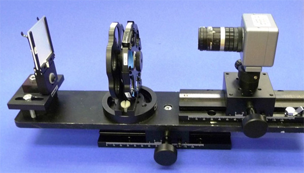
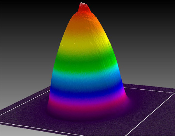
Figure 1. A diffusive target and camera comprise a system for measuring a highly divergent light source. Filter wheels can used to place optical bandpass filters in the light path to selectively measure by wavelength, the output of each source that comprises the light empowered product. (Source: Dentsply)

Target material must be transmissive and diffusive, but not introduce any pattern or structure of its own. Ground glass and flashed opal are common choices for targets. The grain or grit of the material must be smaller than what can be resolved by the imaging system. Targets should also be selected so as not to be damaged or discolored by the light from the device under test.

In the Figure 1, light from the curing lamp is impinged on the target. An imaging lens relays the target image to the camera detector array. The camera collects images of the light intensity distribution of the lamp under test and provides them to the system software for display and analysis. Figure 2 shows the resulting beam profile.

Figure 2. Beam profile of dental curing lamp. (Source: Ophir-Spiricon, LLC)

Figure 3 illustrates the output of two LED based, battery operated curing lights measured with a modified Spiricon laser beam profiling system. The false color scheme represents varying levels of irradiance falling on to the target. The dimensions of the light pattern are defined using percent of energy or percent of peak energy definitions. These measurements provide a sub-set of pixels on which to distribute the total power. The power measurement is divided by the total number of digital counts to obtain a count per intensity scale. From this each pixel is assigned a power over area value.

Figure 3. Profiles of LED based, battery operated curing lights. (Source: Ophir- Spiricon, LLC)

The unit on the left has a total integrated optical power of 310 mW and average power density of 3.26 Watt/cm2. The device on the right has total power of 714 mW and an average irradiance or power density of 1.19 Watts/cm2. The system can be calibrated for total intensity or radiant existence with the use of a integrating sphere and silicon photo diode sensor. The total integrated power is read by Ophir’s BeamGage software application, providing a 2-dimensional map of the intensity distribution of the light source under test. Once calibrated for total intensity and effective pixel spacing, each pixel has a power density value associated with it.

Spatial non-uniformities, in this case due to the placement of the internal light sources, can be plainly seen and quantitatively measured. Many non-coherent light sources can be effectively measured with commercial laser beam profiling systems. By associating a known, externally measured total power (radiant flux) of the device under test with the beam profile, two-dimensional maps of the distribution of the light source can then be made. The use of filters that limit spectral transmission can be employed to measure the distribution of the various sources that comprise the light output from the product. Such measurement systems can be employed to ascertain the goodness of the light source per the application by manufacturers and users of the product. The additional of a spectrometer confirms the wavelength(s) of interest and also assures the spectral output of the device under test falls in the 350 to 1,100nm spectral range of the CCD camera and optics.

Best Practices

A few things to remember. Each wavelength should be measured separately, as the response of silicon CCD cameras is not spectrally uniform. The total integrated power of each spectral contributor should also be measured individually and associated with the spatial profile of that wavelength.

Care must be taken to assure that the camera Exposure and Gain controls are not modified once the calibration of the total radiant flux that is impinging onto the target has been made. These controls change the camera sensitivity thus modify the calibration of the light source.

If filters are used as attenuation devices, the filters must be consistent with the profile and power measurements and not modified once calibrations are made.

It is also important to place something of known dimension is the image plane so that the measurement software can be spatially calibrated. Most laser beam analysis systems allow you to modify the dimension of the pixel to accurately represent the optical minification of the imaging system. The measurement may be compromised when the source to target distance is changed. Not all of the light exiting the source is impinged on the target. As the target to source distance is increased, the amount of light from a divergent source impinging on the target is decreased. This distance must remain constant when comparing light sources.

These techniques may also be used to measure the output of low level light therapy devices. In Figure 4, matrices of LEDs are used in a clinical photobiomodulation products. Again, the total contribution of multiple wavelengths can be combined by measuring each separately. The images can be combined and the individual power measurements added to obtain a useful map of the intensity distribution of the device.

Figure 4. 3D image of the irradiance distribution of a matrix of monochromatic LEDs. (Source: Ophir-Spiricon, LLC)
Contact Us illustration

Have questions? Require assistance?

Click below to to contact Ophir Photonics and we'll get back with you shortly.

Contact Ophir Photonics