M2 Beam Propagation:
Why So Many Different Approaches to Measurement Instrumentation?

Measuring the propagation parameters of a laser beam is an important method of understanding the quality of the laser beam and predicting its performance for various laser applications. For this reason, it is one of the major specifications required by laser users and reported by laser manufacturers. Ophir-Spiricon has been a leader in providing instruments dedicated to this important measurement. There are currently three different instruments available under the Spiricon and Photon brands, and in this article we will explain the differences between them and the reasons for these different approaches to making this measurement. Hopefully, this will assist you in deciding which approach is best for your laser and laser application.

Author:

Allen Cary, Director of Marketing, Ophir-Spiricon

The Measurement

The m² Beam propagation measurement is made by observing how a laser beam behaves when focused with a lens. The ISO 11142 protocol calls for measurements to be made along the z-axis of a beam, both around the waist formed by the lens and additionally at positions at least two Rayleigh ranges¹ away from the beam waist. At least 5 beam measurements are made at the waist and 5 more at the far field positions. From these measurements a curve fit determines the m² value. A perfect Gaussian TEM00 laser beam will have an m² value of 1.

Figure 1. ISO Standard 11146 Method.

What does this mean? When one is focusing a laser beam with a lens, the minimum beam waist achievable is called the diffraction limited beam waist. This waist size is dependent on several factors and can be described by the following formula:

Where, d0 is the minimum or diffraction limited waist size, λ is the wavelength of the laser, θ is the divergence angle of the focus and π is the mathematical constant. As you can see if m² is 1, then it has no impact on the diffraction limit to focus. m² cannot be less than 1.

The Instruments

Spiricon's m²-200 series m² Beam Propagation instrument has been a popular instrument for this measurement for more than a decade. This system is a fully automated test instrument based on the ISO 11142 beam propagation protocols for the measurement of m². It is a CCD camera based system that incorporates automated attenuation and automatically finds the proper measurement points to determine the m² without requiring any operator intervention.

Figure 2. m²-200s.

The Photon NanoModeScan mounts a NanoScan slit based beam profiler on a motion stage and moves the scan head through the beam caustic to make the measurements and fit the m² curve.

Figure 3. NanoModeScan.

The Photon m²-1780 is a unique measurement system also based on a CCD camera. This instrument allows an instantaneous measurement of the entire caustic at the frame rate of the camera.

Figure 4. m²-1780

Why Have So Many Instruments Do the Same Thing?

In reality they don't do the same thing. The m²-200s is a fully automated system that does the measurement reproducibly with no intervention apart from the initial alignment of the laser beam. This makes it very popular with laser manufacturers doing the same measurement on similar lasers. It provides consistent results in a final test environment. There are some shortcomings though. Since it is a CCD based system, it is confined to the UV-Vis and very near infrared wavelength ranges (~266-1100nm). It is also not too good for the lower UV range below 350nm because continuous use in this range tends to destroy the CCD imager relatively rapidly. For this reason, the NanoModeScan may be a better choice for this as well as for infrared sources above 1100nm. Because the NanoScan is available with silicon, germanium or pyroelectric detectors, the NanoModeScan can be used with any wavelength. Additionally the very wide dynamic range of the slit scanning beam profiler, there is no need for the adjustable attenuation. This makes the measurement considerably faster than the m²-200s.

Both the m²-200s and the NanoModeScan use a method that scans the detector through the beam caustic. The m²-200s does this by varying the path length of the beam and successively focusing different parts of the beam path on the fixed CCD imager. The NanoModeScan does this by moving the scanhead itself though the beam caustic. In either case the process consists of multiple beam measurements over a period of time from 20 seconds to several minutes. This requires that the beam be completely stable or the results will be meaningless. Here is where the m²- 1780 differs from either of these approaches. In this system the beam caustic is divided into 10 "slices" and simultaneously measured on the CCD. This allows the whole caustic to be measured at once and the m² value to be determined for every frame of the acquisition. This means that even an unstable beam, or one in the midst of being adjusted can be measured with direct and immediate feedback. It also allows the measurement of the m² of a single pulse of a pulsed or even single shot laser.

In addition to the M² parameter, several other ISO parameters are calculated by all of these instruments. They include:

  • Laser beam waist size and location
  • Divergence angle
  • Rayleigh range

How do they work?

The m²-200s uses a pair of mirrors mounted to a motion stage to vary the path length of the laser beam caustic. This successively focuses different positions in the beam caustic onto the CCD, making the beam size measurements. From these beam measurements the propagation parameters are determined using a fit algorithm.

Figure 5. m²-200s mechanical diagram.

The beam parameters are reported via the dedicated m²-200s software interface

Figure 6. BeamGage m² software screen.

The Photon NanoModeScan uses a similar measurement technique by moving the scanhead successive to positions along the Z-axis of the caustic formed by the test lens.

Figure 7. NanoModeScan diagram.

Again, the propagation parameters are reported by the dedicated NanoModeScan software interface.

Figure 8. NanoModeScan measurement screen showing beam caustic measurements.

Because the NanoModeScan can be fitted with any of the NanoScan beam profilers, it is not limited to any wavelength range. It can be used from UV to far infrared by selecting the proper NanoScan detector type: silicon for UV-Visible, germanium for near infrared (900nm-1700nm) or the pyroelectric for any wavelength of lasers with sufficient power (generally greater than several 100mW).

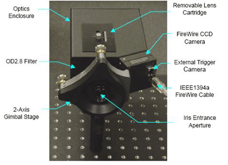
The unique m²-1780 approaches the measurement differently. By using 10 reflective surfaces provided by precisely aligned quartz wedges, the beam caustic is divided into ten slices and simultaneously focused on the CCD detector. This allows the m² and other propagation parameters to be determined instantaneously in realtime. The CCD sensor is divided into 10 sectors, and the beam is aligned to put each beam measurement position into one of these boxes. Once aligned, the software reports the parameters for each frame the CCD acquires. This makes it possible to make real-time adjustments to the laser and watch the results as direct feedback.

Figure 9. m²-1780.
  1. One Rayleigh range is defined as the point on either side of the waist where the beam diameter increases to the square-root of 2 times the waist diameter (i.e., 1.414 d). Two Rayleigh ranges would be the point at which the beam is 2.828 times the waist diameter.
Contact Us illustration

Have questions? Require assistance?

Click below to to contact Ophir Photonics and we'll get back with you shortly.

Contact Ophir Photonics