Assuring Correct Metallurgy in Direct Laser Melting

Additive manufacturing has restructured prototyping, development, and advanced design of mechanical components. Direct Metal Laser Melting, also known as Selective Laser Sintering or 3D Metal Printing, is quickly becoming the standard for designs that cannot be fabricated with traditional metal removal techniques. To create consistent, strong structures using laser-based additive manufacturing processes that meet flyable DOD standards or FDA requirements, the metallurgy must be consistent. In addition, a laser beam of known dimension, power density, and focal spot location is required.

Author:

By Gary Wagner, General Manager, Ophir (U.S.)

To print a metal part, metal powder is drawn on the build area to an exacting thickness while a focused laser beam heats the metal powder to the correct temperature; this fuses the powder.

If the laser power is too low or not applied long enough, the grains of powder do not melt properly; the metal becomes porous and, therefore, weaker. If too much laser power is used or the laser is applied longer than necessary, the laser will drill into the fused powder, reducing the density of the structure. If the focused spot location is before or behind the build plane, or the distribution of the laser power is not optimized, inadequate melting of the metal powder will result. All of these conditions leave you with a part that is not metallurgically correct.

Quality 3D laser printed processes require a laser delivering the correct amount of power, distributed correctly and focused at the correct location. To ensure consistent and structurally sound parts, these parameters should be directly measured before and after any critical part is made.

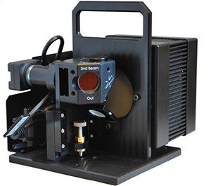
BeamCheck™ is a new, integrated laser measurement system designed to measure critical laser beam parameters for laser-based additive manufacturing systems. The system includes a CCD camera for spatial measurements and a NIST-traceable power sensor that provides a complete analysis of the laser power density profile.

The camera is precisely located at the build plane so that an accurate power density model of the working laser beam can be made. A beam splitter directs a small percentage of the beam to the camera, while the majority of the beam is directed to the integrated power sensor. From these measurements an accurate beam spot size and power density can be derived.

The focused spot location can change as optics in the laser delivery system are heated by the laser beam. In fact, the focused location can move several millimeters over time, changing the effect of the laser beam on the metal powder. BeamCheck measures the thermal focal shift, allowing users to correct additive manufacturing processes before damage is done.

Contact Us illustration

Have questions? Require assistance?

Click below to to contact Ophir Photonics and we'll get back with you shortly.

Contact Ophir Photonics