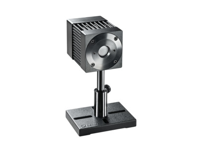
The F80(120)A-CM-17 is a laser Power Sensor Measures High Repetition Rate, Short Pulse Industrial Lasers for Micromachining. It has a high damage threshold for high repetition rate pulsed lasers, 17.5mm aperture and can measure power from 100mW to 80W continuously and to 120W intermittently. The sensor comes with a standard 1.5-meter cable for connecting to Ophir meters.
Continuous operation with ultra-short pulses without diffuser
Additional CAD file downloads are not available for this product.
f80-120-a-cm-17-thermopile-sensor - Drawings
Additional drawings are not available for this product.
Specifications
Product Name
F80(120)A-CM-17
Absorber Type
CM
Aperture Size
Ø17.5mm
Spectral Range
0.248μm-9.4μm
Minimum Power
100mW
Maximum Average Power
80W
Maximum Power Intermittently
120W
Minimum Pulse Energy
50mJ
Maximum Pulse Energy
200J
Response Time
2 s
Maximum Average Power Density
35kW/cm²
Maximum Energy Density <100 ns
0.7J/cm²
Maximum Energy Density 2 ms
45J/cm²
Cooling
Fan
Dimensions
64 L x 64 W x 93 D (mm)
Cable Length
1.5m
CE Compliance
Yes
UKCA Compliance
Yes
China RoHS Compliance
Yes
Features
Choosing a Thermal Sensor
In this short “Basics” video we review the use – and selection - of thermal sensors for measuring low, medium and high laser powers.
Sensors for Measuring Laser Energy
In this short "Basics" video, we review in general the use of pyro-electric sensors for measuring laser pulse energies.
Product Overview: F80(120)A-CM-17 High Damage Threshold Laser Power Sensor
If you need to measure the power of high repetition rate lasers with very short pulses (typical in many micromachining applications) – and you want a sensor that will survive the experience – the new F80(120)A-CM-17 from Ophir may be exactly what you need. Get a short overview in this video.
On-demand Webinar: Laser measurement solutions for material micro processing applications
If you use lasers in material "micro processing" applications – such as drilling via holes in PCBs, OLED display "lift-off", cutting of smartphone cover glass – you already know how difficult the challenges are.
First, clean the absorber surface with a tissue, using Umicore #2 Substrate Cleaner, acetone or methanol. Then dry the surface with another tissue. Please note that a few absorbers (Pyro-BB, 10K-W, 15K-W, 16K-W and 30K-W) cannot be cleaned with this method. Instead, simply blow off the dust with clean air or nitrogen. Don't touch these absorbers. Also, HE sensors (such as the 30(150)A-HE-17) should not be cleaned with acetone.
Note: These suggestions are made without guarantee. The cleaning process may result in scratching or staining of the surface in some cases and may also change the calibration.
The Ophir specification on accuracy is in general 2 sigma standard deviation. This means, for instance, that if we list the accuracy as +/-3%, this means that 95% of the sensors will be within this accuracy and 99% will be within +/-4%. For further information on accuracy see calibration procedure tutorial.
Thermal sensors for intermittent use such as models 30(150)A, L40(250)A-BB-50 etc. can be used up to the powers in parenthesis for a period given approximately by the following formula: The rule of thumb is that you can use the sensor for 1 minute/watt/cm3 of sensor. So for 150 watts for 30(150)A you have 1minute*165cm3/150watt =~ a little over one minute. The sensor finder program calculates the allowability of intermittent use when the user fills out the choice for duty cycle.
The damage threshold of thermal sensors does depend on the power level and not only the power density because the sensor disc itself gets hotter at high powers. For instance, the damage threshold of the Ophir broadband coating may be 50KW/cm2 at 10 Watts but only 10KW/cm2 at 300W. The Ophir specifications for damage threshold are always given for the highest power of use of a particular sensor, something which is not done by most other manufacturers. This should be taken into account when comparing specifications. The Sensor Finder takes the power level into consideration when calculating damage threshold.
Ophir meters and sensors are calibrated independently. Each meter has the same sensitivity as the other within about 2 tenths of a percent. Each sensor is calibrated independently of a particular meter with its calibration information contained in the DB15 plug. When the sensor is connected to the meter, the meter reads and interprets this information. Since the accuracy of our sensors is typically +/-3%, the extra 0.2% error that could come from plugging into a different meter is negligible and therefore it does not matter which calibrated meter we use with a particular calibrated sensor.
It is not recommended to choose a sensor if it is very close to the damage threshold if there is an alternative, since laser damage is not an exact figure and depends on many things. Use the Sensor Finder to find the best match where you are preferably below 50% of the damage threshold.
The main unique capability of the CM absorber is its ability to withstand very short pulses at high rep rates, which “regular” absorbers have difficulty with. When pulses are short (say, nsec and shorter), even low energy pulses still mean very high “peak power” or instantaneous power, and this can cause damage to an absorber through non thermal mechanisms (such as ablation). The CM absorber is significantly more durable under such conditions than most other absorbers. The following guidelines can help you when choosing (together with using the Sensor Finder):
For repetitively pulsed beams with short pulses, high rep rates, ≈ low energies (roughly mJ range or lower): CM (A typical application would be micromachining.)
For repetitively pulsed beams with short pulses, low rep rates, ≈ high energies : PF
For repetitively pulsed beams with short pulses, high rep rates, ≈ high energies : SV (very little can really withstand such conditions; the unique SV absorber is the top of the line)
In theory, if a beam is completely parallel and fits within the aperture of a sensor, then it should make no difference at all what the distance is. It will be the same number of photons (ignoring absorption by the air, which is negligible except in the UV below 250nm). If, nevertheless, you do see such a distance dependence, there could be one of the following effects happening:
If you are using a thermal type power sensor, you might actually be measuring heat from the laser itself. When very close to the laser, the thermal sensor might be “feeling” the laser’s own heat. That would not, however, continue to have an effect at more than a few cm distance unless the light source is weak and the heat source is strong.
Beam geometry – The beam may not be parallel and may be diverging. Often, the lower intensity wings of the beam have greater divergence rate than the main portion of the beam. These may be missing the sensor's aperture as the distance increases. To check that you'd need to use a profiler, or perhaps a BeamTrack PPS (Power/Position/Size) sensor.
If you are measuring pulse energies with a diffuser-based pyroelectric sensor: Some users find that when they start with the sensor right up close to the laser and move it away, the readings drop sharply (typically by some 6%) over the first few cm. This is likely caused by multiple reflections between the diffuser and the laser device, which at the closest distance might be causing an incorrectly high reading. You should back off from the source by at least some 5cm, more if the beam is not too divergent.
Needless to say, it’s also important to be sure to have a steady setup. A sensor held by hand could easily be moved around involuntarily, which could cause partial or complete missing of the sensor’s aperture at increasing distance, particularly for an invisible beam.
Water cooled sensors will hardly be affected by ambient temperature since the sensor temperature is determined by the water temperature. Ophir convection and fan cooled sensors are designed to operate in an ambient environment of 25°C up to the maximum rated power continuously. When operating at its maximum rated power, the sensor’s body should typically not exceed about 80°C in temperature.
Note: If the room temperature is higher than 25°C, then the maximum power (at which the sensor can be safely operated) should be derated accordingly from the specified maximum (since dissipation of the heat from inside the sensor to the surrounding air will be more difficult). For example, if the room temperature is 35°C, then the maximum power limit should be (80-35)/(80-25) = 82% of maximum rated power as given in the sensor’s spec.
Accessories
Sensor Connector to BNC Adapter
The SH to BNC Adapter allows the connection of an Ophir sensor to a current or voltage measuring device for measurement of the raw sensor analog output. A current meter should be used for photodiode sensors. Current or voltage meters can be used for thermal sensors.
Compare
Description
Compatibility
Drawings, CAD & Specs
Avail.
Price
7Z11010BNC Adapter, DB15 Optical Sensor Connector
UNIVERSAL
8 Weeks
$92.00
Showing 1 to 1 of 1 entries
Thermal Sensor Cables
Order a cable of a different length along with the sensor to receive a cable other than the standard 1.5 m length.
Compare
Description
Compatibility
Drawings, CAD & Specs
Avail.
Price
7E01122AThermal Sensor Cable, 3 m Length, Connect to Power Meter
In order to provide better service and products, please provide the following brief information. Any future resource requests will be automatically available.
Password Reset
Enter your email address below to reset your account password.
Password Reset
Email Verification Required
Cart Items Updated
Remove Product
Remove this product from your comparison list?
Check Order Status
Provide an order number and postal code to check the status of an order or download an invoice for an order that has shipped. Login to view your complete order history.
Sign In Required
To access this and other valuable technical resources, please sign in or register for a new online account.